Select Page

DC Link Chokes

1000 Volts DC – Filters 360 Hz Ripple Current – Economical, Versatile Power Quality Solutions For Variable Speed Drives & Inverters.
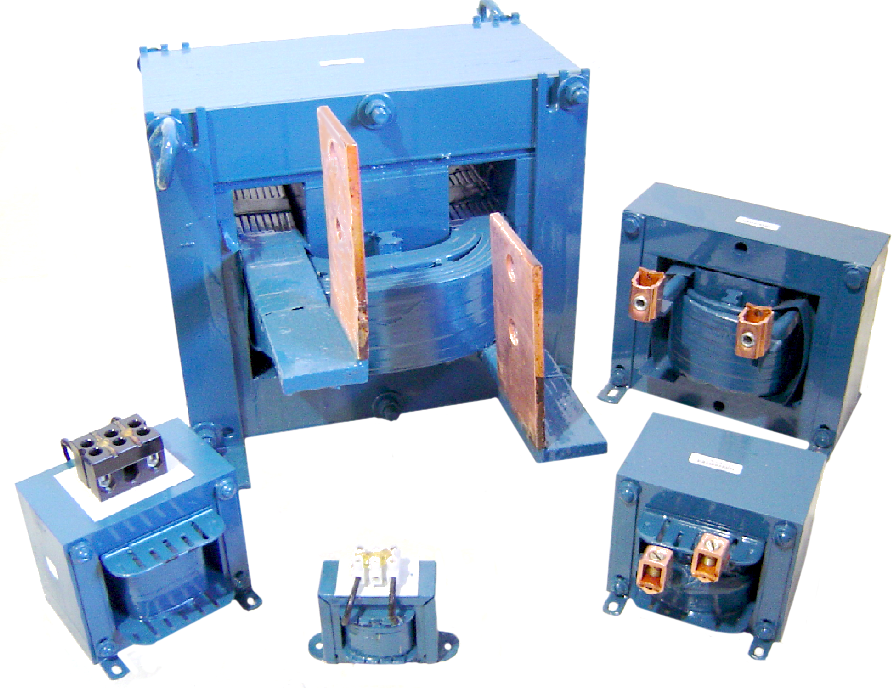
DC Link Choke

DC Link Chokes

Control DC bus voltage right in your VFD

RELATED LINKS:

Selection Brochure
Solutions Catalog
User Manual

 MTE’s DC LINK CHOKES, also referred to as DC line chokes or inductor chokes, are an economical means of filtering and controlling the DC bus voltage and current in a variable speed drive/inverter. They help reduce AC input line current harmonic distortion while absorbing DC bus voltage spikes. Link Chokes add protection and filtering but should not be considered a direct alternative to AC input or output reactors.

MTE’s DC LINK CHOKES offer the advantage of maximizing the circuit inductance for power quality reasons, but without causing an AC input line voltage drop. Link Chokes can be used individually, typically on the positive DC bus, or in pairs with one each on both the positive and negative bus. When two DC Link Chokes are used on the bus, the inductance is additive. You will need twice as much inductance on the DC bus as used on the AC input (per phase) to accomplish the same performance experienced with AC input reactors. For best performance combine the use of both an AC input reactor and a DC Link Choke.

NOTE: While DC Link Chokes increase the internal filtering and have the ability to absorb spikes, because of their circuit location they do not protect the input bridge rectifier. They do not offer protection for the inverter output circuit due to their location on the DC bus.

SPECIAL FEATURES:

  • Solid Copper Box lug type terminals on most sizes
  • Specially constructed and epoxy impregnated for low noise
  • Customized ratings also available—contact factory for custom mounting, inductance, current or ripple requirements

Use DC Link Chokes In Applications Such as:

  • AC PWM inverters/drives
  • DC to AC inverters
  • Variable frequency motor drives
  •  Electrical vehicle inverters

Use MTE DC Link Choke to:

  • Reduce AC input line harmonics
  • Help meet IEEE-519 limits
  • Absorb voltage/current spikes
  • Reduce AC ripple on DC bus
  • Reduce dv/dt and di/dt rates
  • Solve nuisance over-voltage tripping
  • Reduce DC Bus transient over-voltage

1000 Volts DC
Filters 300/360 Hz Ripple Current

Selection Tables:

Click part numbers for cad files of DCA Link Chokes

DC AMPSINDUCTANCE
mH
CAT. NO
1
1
1
35.00
60.00
80.00
1RB001
1RB002
1RB003
2
2
2
2
10.00
15.00
20.00
50.00
2RB001
2RB002
2RB003
DCA000204
3
3
3
7.00
11.00
13.00
TEST-1RB001
TEST-1RB002
TEST-1RB003
4
4
4
4
5.00
12.00
15.00
25.00
4RB001
DCA000402
DCA000403
DCA000404
9
9
9
9
2.00
3.22
7.50
11.50
9RB001
DCA000902
DCA000903
DCA000904
12
12
12
12
1.00
2.10
4.00
6.00
DCA001201
DCA001202
DCA001203
DCA001204
18
18
18
18
18
0.65
1.375
2.75
3.75
6.00
DCA001801
DCA001802
DCA001803
DCA001804
DCA001805
25
25
25
25
25
0.45
1.00
1.275
1.75
4.00
25RB001
25RB002
DCA002504
DCA002503
DCA002505
32
32
32
0.85
1.62
2.68
DCA003201
DCA003202
DCA003203
DC AMPSINDUCTANCE
mH
CAT NO.
40
40
40
40
0.50
0.75
1.00
2.50
DCA004001
DCA004002
DCA004003
DCA004004
50
50
50
50
0.625
0.97
1.35
2.00
DCA005001
50RB002
DCA005003
DCA005004
62
62
62
62
62
0.35
0.61
0.67
1.20
1.50
DCA006201
DCA006202
62RB003
62RB004
62RB005
80
80
80
80
80
0.31
0.40
0.50
0.75
1.25
80RB001
DCA008002
80RB003
80RB004
DCA008005
92
92
92
0.20
0.60
1.00
DCA009201
DCA009202
DCA009203
110
110
110
0.25
0.30
0.45
110RB001
DCA011002
DCA011003
125
125
125
125
0.11
0.22
0.50
0.85
125RB001
DCA012502
125RB003
125RB004
150
150
150
150
0.15
0.22
0.32
0.65
150RB001
DCA015002
150RB003
DCA015004
DC AMPSINDUCTANCE
mH
CAT NO.
200
200
200
200
0.12
0.21
0.40
0.50
200RB001
DCA020002
200RB003
200RB004
240
240
240
0.09
0.25
0.35
240RB001
240RB002
240RB003
300
300
300
0.08
0.135
0.32
300RB001
300RB002
300RB003
450
450
450
450
0.055
0.11
0.14
0.25
450RB001
450RB002
450RB003
450RB004
500
500
500
500
0.043
0.09
0.14
0.19
500RB001
500RB002
500RB003
500RB004
600
600
600
0.04
0.11
0.18
600RB001
600RB002
600RB003
700
700
700
0.044
0.06
0.15
700RB001
700RB002
700RB003
850
850
850
0.036
0.065
0.11
850RB001
850RB002
850RB003

Specifications:

  • UL-508 Component recognized (File #E180243)
  • 1000 Volts DC maximum
  • For ripple frequency of 300hz or 360hz
  • Suitable for 40 C ambient temperature
  • Class B Insulation System (130C)
  • Suitable for ripple current of 10% peak-to-peak

Special Features:

  • Solid Copper Box lug type terminals on most sizes
  • Specially constructed and Epoxy impregnated for low noise